Horizontal Quad Antenna
By: Eli Kovo, 4X4LH (originally published in the IARC newsletter 08/2015 “HaGal†and used with permission of the author.  Translated by: Earl, VA6TJ)
I recently came across an article in an issue of “73 Magazine†from 1978 raving about an antenna called “The German Quad†which [at that time] was used by about half the hams in Germany.  Below I summarize the main points of the article.
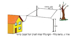
The first thing about this antenna is that it works without a tuner on 6 bands, from 10m to 80m and also on 2m. I could not find confirmation that it works on 6m however I am confident that it will also transmit on that band. Compared to a symmetrical dipole, the horizontal quad has the advantage that it can be fed anywhere, even at a point close to the shack as in illustration 1.
As a folded loop antenna it receives 25 db less man made noise. Similar to other loop antennas with an empty space in the center it does not pick up signals coming straight down from the ionosphere such as QRN and nearby strong signals sources.
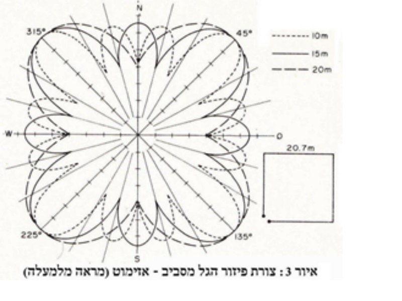
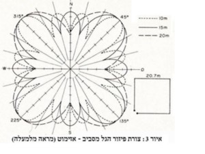
Polarization is horizontal and radiation is omnidirectional at a low angle. The shape does not need to be square however the area / aperture should be maximized. If the outer perimeter is a circle that should be optimum and would add about 1 dB over a square – however this is difficult to achieve.
Optimum height for the 80m band should be about 10m. Ground effects and the distance between the radiator and ground multiply the bottom and upper lobe unifying them into the main lobe thereby contributing to the effect of the transmitted signal. For higher frequencies a height of 5 – 10 meters will be sufficient.
Gain over a dipole at the same height is said to be 6 dBd or about 2 S units [I can see this effect on 20m with my loop. VA6TJ]. Compared to DL3ISA’s 3 band 2 element antenna an improvement of 6 – 10 dB was found in favor of the horizontal quad. The other measurement DL3ISA made was between the horizontal quad and a ¼ wave ground plane where the quad was > 12 dB better. [polarization effect ?]
The impedance of the loop is about 100 ohms. One suggested feed method is bringing the feed close to the shack with very low loss 450 ohm ladder line to a tuner.
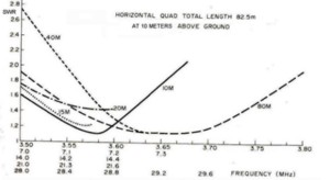
Here we can make a simplifying assumption: don’t use coax to feed a multiband antenna because on some of the bands, which are not exact multiples, SWR will be slightly increased.  See figure 2.
A ham superstition is that open wire feed line radiates more than shielded coax.  Incorrect. The phase of the current on one side of the open wire feed is 180 degrees from the other side and this internal balance cancels its ability to radiate. On the other hand losses for 100 m of open wire feed are only 1% of loss for a similar length of coax. A space of 6 cm between the feed lines will give an impedance of about 450 ohms.
As we saw above, each leg of the quad is ¼λ so if you are short on space build it for the 40m band with sides only 10.5 meters long and if your lot is really tiny try 20m….
Antenna wire should be multi strand and can be insulated. To take the velocity factor into account reduce the calculated length for the lowest frequency band by 4% (0.96 * λ).
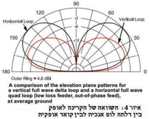
The same antenna can be erected in a different configuration: split in two with the halves fed out of phase. This modification yields improved gain and bandwidth and reminds us in principle of the W8JK antenna. The length of each side shown in figure 5 is appropriate to 30m but it also will work well on 20m and higher frequencies.
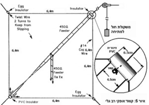
If you have ceramic or glass insulators available they are recommended; if not sections of PVC pipe also work. With a bit of advanced planning you can use one piece of wire about 43 meters long threading it through the insulators thereby avoiding soldered connections that could cause problems down the road. The only soldered connections will be to the 450 ohm ladder line in the center of the bridge. Don’t forget to twist the feed line in the bridge. It seems to me that a balanced tuner could be used for 20 and 40m.
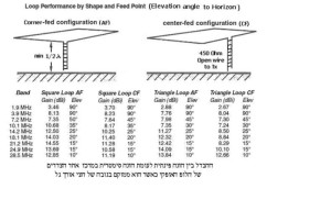
We should also point out that horizontal or vertical delta loops are members of this antenna family. Length of the wire is also a λ. I have been using a 20m vertical delta loop that gets me replies from DX stations with my first call and 100 W from my Icom 751A. In the table below we see the differences between corner fed and center fed antennas, square and delta loops.