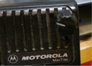
Maxdroid
Modification to add a digital display and continuous frequency selection to VHF/UHF Maxtrac transceivers.
By
Avinoam Albo, 4X1HF Avinoam.albo@gmail.com
December 2014
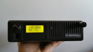
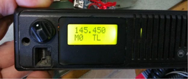
Conversion of a Maxtrac to a transceiver with display and frequency selection
In this article I will explain how to convert the venerable Maxtrac to a rig more user friendly to radio amateurs. The modification requires  the addition of only a few inexpensive and easily available components. When the modification is completed you will have a rig with digital display and frequency selection enabling continuous  coverage over the whole range of frequencies  where the VCO locks. An external programmer is no longer needed.
Disclaimer: Carrying out the modification described requires basic electronics skills. Any modifications are the sole responsibility of the technician. This modification will likely void type certification for commercial radio service.  This article does not make any specific claims or recommendations.
Specifications of the transceiver after this modification
- Digital display
- Continuous frequency selection
- Selection of transmitter output power (2 levels or more)
- Selection using VFO or memories
- Selection of VFO frequency steps (5K, 10K, etc.)
- Receive PL (on/off)
- Scanning and saving frequencies to memory (future)
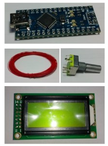
Required ComponentsÂ
- Maxtrac VHF or UHF
- Arduino Nano 328 controller
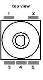
- Rotary encoder
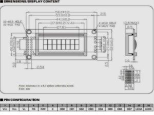
- LCD 08 X 02 (8 characters x 2 lines)
- 3K, 4.7K, 8.2K, 10K resistors
- Fine gauge insulated hookup wire such as wire wrap wire
Programming the transceiver
After the modification all the functions continue to work (including programmed functions) with the exception of operating frequency, output power and enable / disable receive PL.
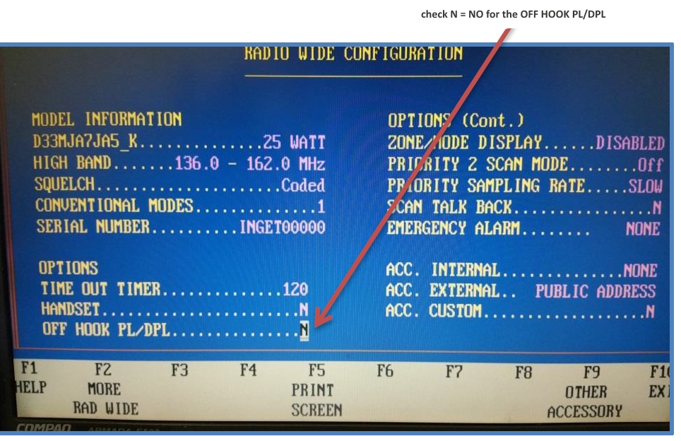
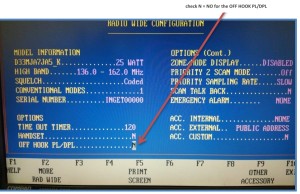
After reading the radio configuration with the help of programming software and cable,
enter the “RADIO WIDE CONFIGURATION menu and in the OFF HOOK PL/DPL line mark N (no).
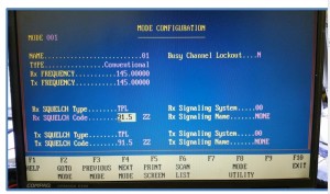
In the MODE CONFIGURATION menu it’s recommended to erase all the channels (MODE) and to leave only one channel with receive and transmit PL of 91.5 Hz. The transmit and receive frequencies are not important because they will be set by the new controller, and not the original Maxtrac circuitry.
Removing the original display from the transceiver
We must first remove the original display and push buttons to make room for the new LCD display. Open the transceiver and disconnect J9. You will then be able to remove the old display by taking out the 4 screws that secure it in place.
On the push button board there are pull up resistors for each of the 5 buttons and therefore it is necessary to add a 10K resistor to the pins revealed by removing the board. One end of the 10 K resistor goes to pin 9 and the other end connects pins 3,4,5,6, and 7 as shown in the photo.
Cancelling frequency control by the original processor Â
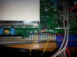
Since we wish to control the transceiver’s working frequency with the new controller, it is necessary to cut two traces on the board and then connect our controller to the logic board. Locate the row of pins connecting the logic board to the RF board (see photo).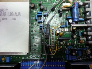
We need to connect to the points marked 6,7 and 8 in order to control transceiver frequency. Cut the traces going to pins 6 and 7 as shown in the photo. This can be done with a small razor knife or scalpel.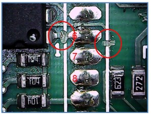
We will connect points 6, 7 and 8 to the Arduino controller as shown in the table below. The controller will be located just behind the new LCD display so cut the lead lengths appropriately. If you are not familiar with Arduino controllers take a look at several YouTube videos and try some basic configurations. This will give you an understanding of the Arduino controller pin designations used below.
| Arduino |
Maxtrac |
| D5 |
6 |
| D6 |
7 |
| D7 |
8 |
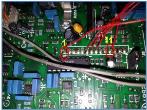
We will provide the Arduino control with voltage using pins from the same row connecting the logic and RF boards. Pin 1 = +12V and pin 11 = Ground. See photo:
| Arduino |
Maxtrac |
| Vin |
1 |
| GND |
11 |
TX/RX and PL
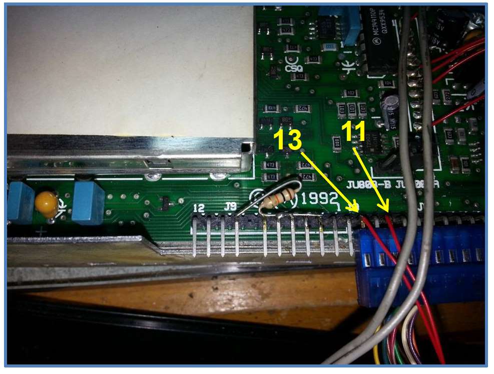
Next we will connect to points that allow reading the TX/RX status and enable / disable of the receive PL. To do this we need to connect to J8, the connector between the microphone connector board and the logic board. Make the connections as per the table:
| Arduino |
Maxtrac |
| D8 |
J8-11 |
| D9 |
J8-13 |

Connections are shown in the photo.
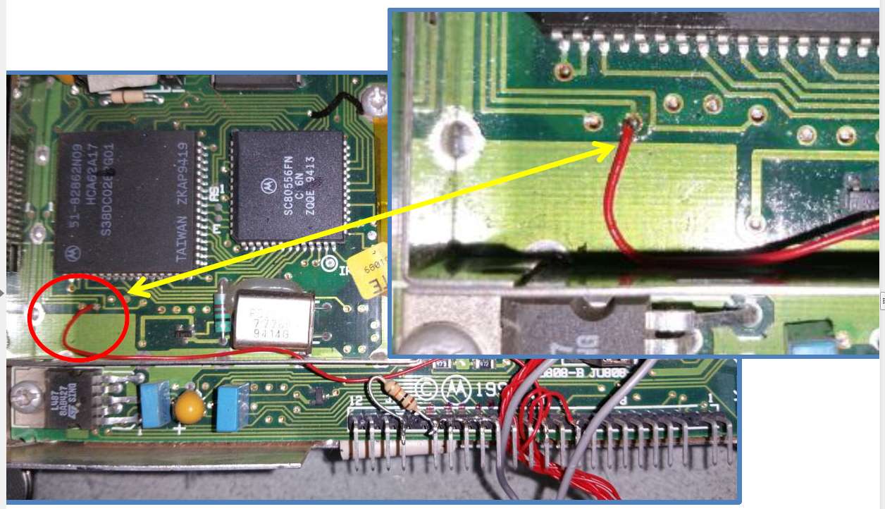
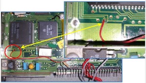
Next we need to know when a received signal has opened the squelch. To do this we connect Arduino pin D10 to the solder pad shown in the photo.
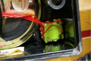
Transmit Power
If we wish to add transmit power selection (high/low) we need to make the following change – you can skip this step if you wish to leave transmit power selection to the Maxtrac programming. It is important to note that the Maxtrac reduces transmit power on long transmissions without reference to the temperature of the final amplifier. This modification cancels this time/power function and gives us direct control of output power. Unsolder the two resistors shown in the photo. Next mount the new resistors as follows:
We can change transmitter power by changing the resistor values. In a high power Maxtrac, by using resistors 3.3K, 4.7K and 8.2K we can select between 20W out (LOW) and 40W out (HIGH). If this modification results in too high a power level the 3.3K resistor can be changed for a 4.7 K resistor.
[there have been problems reported with this mod. beware]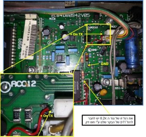
Connect this lead of the 8.2K Resistor to D11 on the Arduino
Supply voltage to one side of the 3.3K resistor using a thin wire to this point
Connecting the new LCD to the Arduino controller
Connect the LCD to the Arduino controller with thin wires as per the table.
| Arduino |
LCD |
| GND |
1,5 |
| 5V |
2 |
| A0 |
4 |
| A1 |
6 |
| A2 |
11 |
| A3 |
12 |
| A4 |
13 |
| A5 |
14 |
Contrast
To control LCD contrast connect a 10K potentiometer with one side to ground (pin 1), the other side to +5V (pin 2) and the wiper (middle pin of the potentiometer) to pin 3. If your LCD has back lighting (16 pins, connect pin 15 to +5 V and pin 16 to ground. If the backlighting is too bright insert a resistor in series with pin 15. When first connected you may not see anything on the LCD, in many cases I have had to adjust the potentiometer to make the display visible.
Connecting the encoder
The encoder will be located in the upper right hand corner of the front panel. Cut the lead lengths appropriately and connect as per the table:
| Arduino |
Encoder |
| GND |
1 |
| D3 |
2 |
| D4 |
3 |
| GND |
4 |
| D2 |
5 |
|
|
|
|
Â
Adapting the front panel
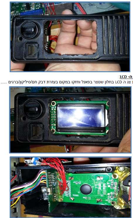
After removing the push buttons and original display the panel must be adapted to fit the new LCD display and the rotary encoder. With the aid of a nibbling and/or cutting tool remove the excess plastic to form a window as shown in the photo.
 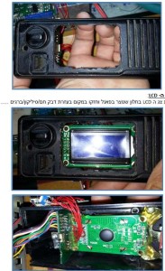
Installing the LCD
Position the new LCD in the window and fasten it with hot glue / RTV silicone or screws. See photos.
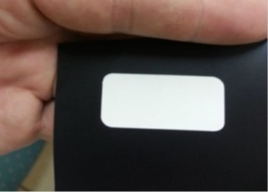
Framing the LCD
Cut a piece of transparent plastic / perspex / polycarbonate to cover the opening in the panel (see photo). Prepare a black mask whose outside dimensions match the clear plastic window and inside opening dimensions reveal the display area of the LCD. Wide black PVC electricians tape could be used. Secure the clear plastic to the front of the panel with hot glue or silicone RTV.  The finished frame installed is shown in the photo below.

Installing the rotary encoder
Remove one of the screws retaining the loudspeaker and drill a hole for the encoder shaft as shown. It will be necessary to cut back some plastic to make room for the encoder.


Â
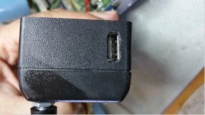
USB connector
It is possible to install a USB connector to be able to update the Arduino controller’s firmware without opening the radio. See photo.
Firmware
sketch
Latest version of the firmware is available. Write to:  Avinoam.albo@gmail.com